This is a guide how to modify an old AT- or ATX-PSU to an adjustable power supply from 2.4 to 23 volts. Those old power supplies have become useless. The maximum output current depends on the performance of the PC power supply. My modification works only, if the PSU has as regulator IC a KA7500, KA7500B, TL494 or DBL494.
Preliminary Note: This modification guide is still under development. The problem is, that every single PSU has different protection circuits. Without wiring diagram it is hard to figure out, how the circuit works in details. Not every ATX or AT power supply is suitable for the modification. My modification has some disadvantages in the meaning, that the power supply is no longer protected against short circuits, too high voltage, too high current and high temperature. Many ATX power supplies are better protected against hazards than AT power supplies in this regard.
My modified PSU is still in the test stage.
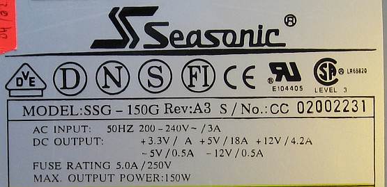
The label of my AT power supply provides information about the performance.

The housing of the AT power supply, which I used for my experiments.
Safety instructions and warnings: Inside Switching power supplies occure high voltages and high currents, which can be fatal for your live or can cause a fire. The modification may only done by professionals, which can realize the dangers and know what they are doing. Any liability and warranty is excluded. Even hours after the shutdown of a switching power supply, the electrolytic capacitors in the primary circuit can still be charged with several 100 volts. They should be discharged with a 230 volt bulb. The switching power supplies should always operate with a protective conductor. The electrolytic capacitors in switching power supplies can explode after the first power on, when the unit was not in operation for a long period.
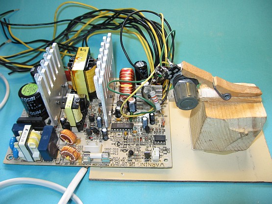
The board of the AT power supply before conversion. The thick cables have to be cut off with the expection of a few black and yellow cables.
How the modification works: The pin 1 of the regulator IC KA7500 is normally connected to a resistor network, which itself is connected to the output voltage terminals of +5 volt and +12 in order to adjust this voltage by the regulator. This is the feedback loop we have to modify. Therefore cut off the pin 1 of the KA7500 from all other components and connect pin 1 to the sliding contact of the potentiometer. The two reminding terminals of the potentiometer have to be connected with the ground and the +12 volt output voltage.
I saw this modification on http://boginjr.com/electronics/lv/atx-mod/, where the mod was realized with an old ATX PSU. The site is worth reading. However I made my mods with an old AT PSU and it seems to be working as well.
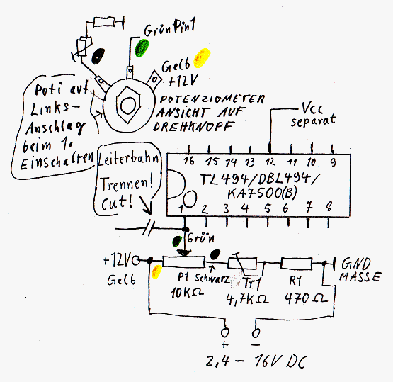
The principle of the modification: Pin 1 of the regulator IC KA7500 has to cut off from all other components. With the potentiometer P1 you can adjust the output voltage from 2.4 to 16 volts. The resistor R1 and the trimmer potentiomer Tr1 reduce the maximum output voltage to 16 volts, because the electrolytic capacitor on the +12 volt output terminal is only suitable for a maximum voltage of 16 volts. With this modification you can adjust the output voltage (yellow cable) from 2.4 to 16 Volts.
Make shure that the regulator IC is supplied by a separate working voltage. This should be checked before you begin with the modification. In my PSU the regulator IC obtaines its working voltage from a separate stabilized voltage source.
In the worst case the output voltage can rise up to 30 volts, if the feedback loop ist broken. This may have serious consequences. The electrolytic capacitors may explode or destroyed by overvoltage.
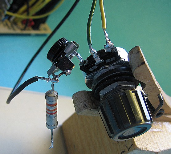
In this way the potentiometer has to be connected. The sliding terminal is connected to pin 1 of the regulator IC. The right terminal of the potentiometer (yellow cable) is connected to the +12 volt output. The 3300 ohm resistor is not connected on this picture, because I did not need it.
The very first power up: The cables are to be connected as described in the graphic and the picture. If you look in front of the knob, the right terminal of the potentiometer has to be connected to the +12 volt output terminal (yellow cable). Before you switch on the device, the potentiometer schould be turned to the left. Than you can rise the voltaga carefully. Don´t rise the voltage to more than 16 Volts in order to prevnent damages to the electrolytic capacitors.
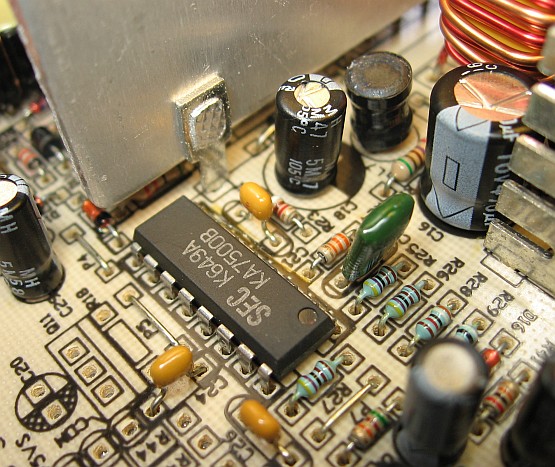
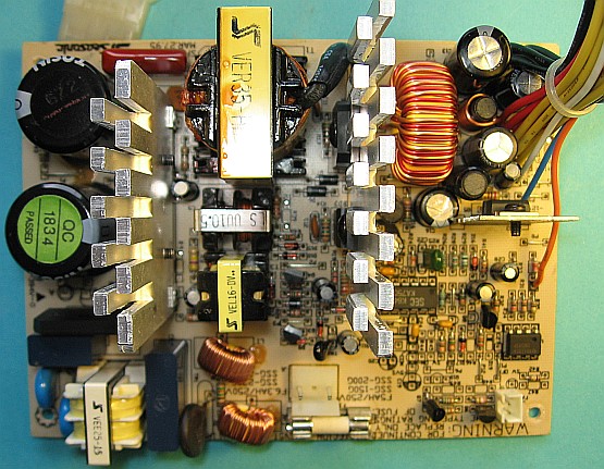
The regulator IC is located close to the output cables on the printed circuit board.
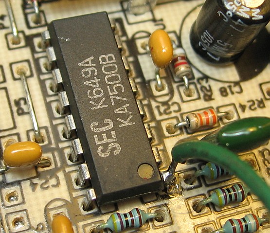
The green wire at pin 1 of the regulator IC is connected to the sliding terminal of the potentiometer. Pin1 has no connections to any other components.
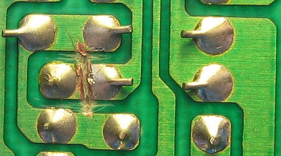
A scratch with a screwdriver disconnect pin 1 of the regulator IC from all other components.
Short circuit protection : The question is, if the modified PSU is still short circuit proof, which is a must for a lab power supply. In order to find out this, I connected a 3 Ampere fuse to the output terminals. When the PSU shuts down the short circuit protection seems to be working.
Maximum output voltage only up to 16 volts: In my PSU, the maximum output voltage was limited by 12 volts for savety reasons. If you tried to tune more than 12 volts the psu shuts down. The reason is a overvoltage protection circuit, which you have to switch of. Therefore I desoldered on pin of a smal diode, which was connected to +5 Volts. The result was, that the maximum output voltage was now 23 Volts. Of course you have to replace some 16 Volt electrolytic capacitors.
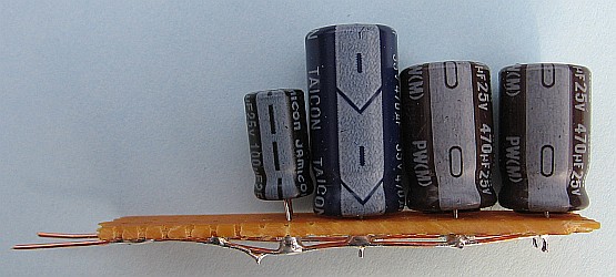
This construction of parallel connected 25 volt capacitors (see text) replaces the 16-volt capacitor at the former +12 volt output terminal.
After this modification the short circuit protection did not work anymore! In case of a short circuit the PSU is damaged!
The maximum out current: My old 150-Watt-PSU could generate 6 Amperes between 6 and 16 Volts output voltage, which was very stable and went down 100 mVolts by connecting a 6 Ampere load.
By disconnecting a small diode the overvoltage protection circuit was shut down and output voltages more than 12 Volts where possible.
Avoid Interferences to radio frequeencies: My modified PSU interfered with FM radio. In order to avoid this, the whole circuit has to be schielded in a metal case.
Conclusion: The modification of a switching power supply circuits with unknown details is not as easy as you may think. By the way is a the high output current not very often an advantage in the lab, because the high current can cause severe damages, if you make a mistake.
Meanwhile, I have another 200-Watt ATX power supply on my workbench. I hope I suceed in modifying it. When the output voltages rises to 5 Volts the PSU started to whistle. Sometimes it is not easy to make a modificataion.