With a few modifications and two additional resistors you are able to modify an old AT or ATX PC power supply unit to a stabilized 13.8 Volts / 20 Amps power supply.
Some security advices: There are high voltages inside the housing, which can result in a lethal situation. Before opening the housing of a pc power supply unplug the power cable and turn off the switch on the back. Discharge the capacitors of the power supply by attaching a 100 ohm resistor between a black and red wire on the output side. However the high voltage capacitors on the input side can be still charged. The best way to uncharge all capacitors is by letting the power supply sit unconnnected for a few days. The modification is at your own risk.
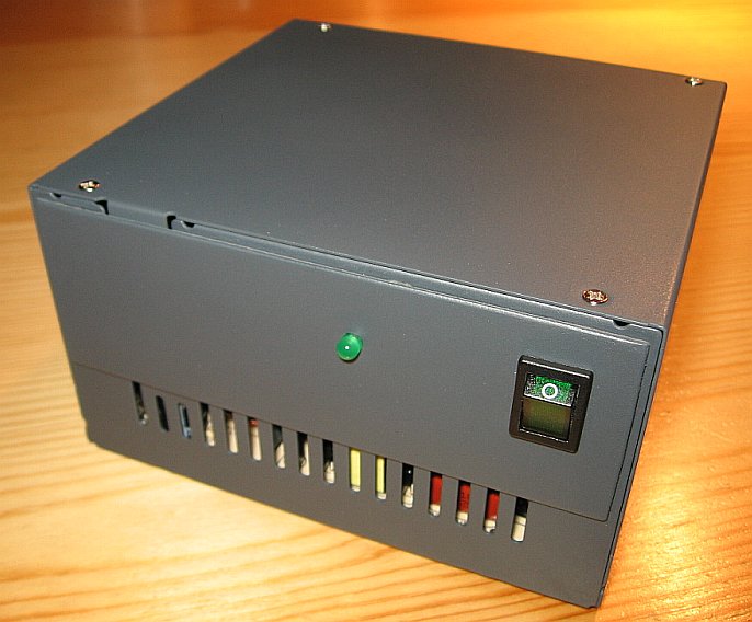
Modified AT power supply. The new front is made by a peace of pcb.
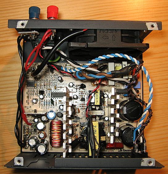
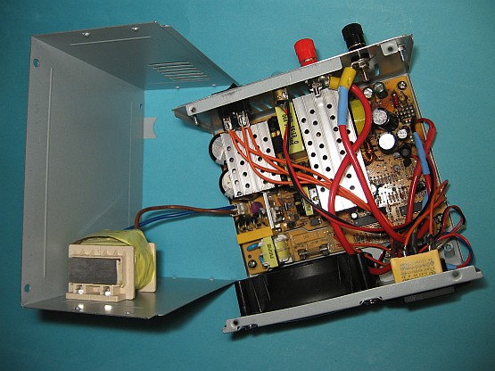
Inside of the modified pc power supply.
The difference of AT and ATX in practice: There exists two versions of pc power supplies. The older versions is called AT and the newer one is called ATX. Both are switched-mode power supplies and the modification works in the almost same way. Both versions provide several voltages. Only the +5 V output ist regulated and serves up to 30 A. Our goal is to achieve stabilized 13,8 Volt 20 Amps ore more in order to charge car batteries or to get a power supply for amateur radio transceivers with 100 Watts RF output. A general requirement of AT type supplies is a minimum load for the supply to stay in operation. If you want to test a PC power supply you have to connect a load resistor between ground (black wire) and +5 V (red wire). The minimum current is about 1 Amps. Instead of the load you can take a 12-Volt-lamp. After the modification you don´t need the load. An ATX power supply has a green wire for power up. Connect the green wire always with any black wire. All black wires are connected to ground. Otherwise the ATX power supply will not work. The older AT power supplies don´t have a green wire. AT power suplies can achieve up to 14.2 Volts after the modification. However ATX power can only supply up to 13.8 volts because they have more internal regulators, which for security reasons avoid output voltages over 13.8 volts. 13.8 volts are sufficient for charging car batteries.
The principal of modification in brief: An unmodified AT or ATX pc power supply has +12 volts (yellow wire) unregulated and +5 volt (red wire) regulated. The modification changes the output from +12 volts unregulated to +13.8 volts regulated. Therefore you insert two resistors which works as voltage divider. The voltage devider reduces the 13.8 volts between the yellow and black wire to 5 volts, which are connected with input of the 5 Volts regulator. In other words: The tap of the voltage divider is connected to the input of the 5 volts voltage regulator. The 5 volts output is cut away and not in use.
How to modify the pcb board and to insert the voltage divider for ATX and AT power supplies (klick here for higher resolution).
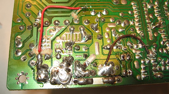
How to do? Remove the pcb board from the case. Unsolder all the cables on the output side and remember which big solder pads where connected to which wires, so you can identify solder pads for the red, black, yellow and green cables. Sometimes you have more than one pad for the same color. If so connect together all the pads, which have the same color.
If you have an ATX power supply, connect the green pad with ground (black wire) by a piece of wire and connect always the orange pad with the brown pad.
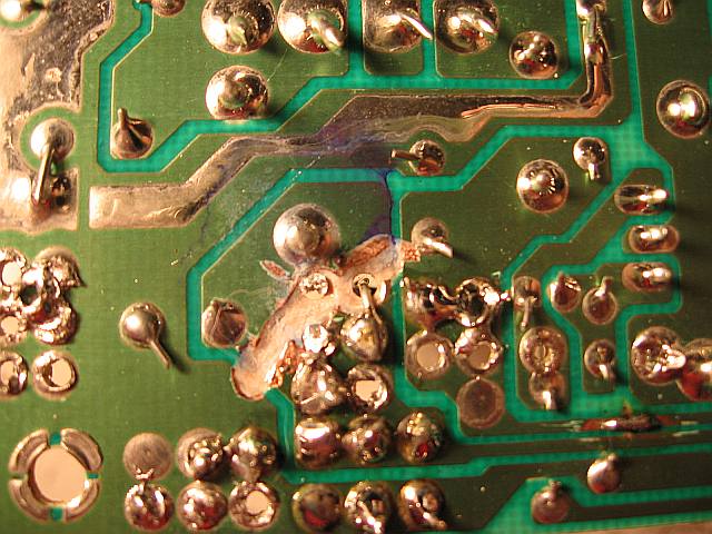
The “red” solder pad for +5 volts is devided into two pieces by scratching with a sharp skrewdriver.
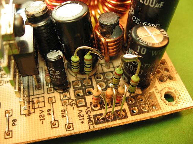
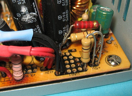
The new voltage devider.
Modifying the pcb board: The next step is to isolate the red +5 volt pad by cutting the pcp trace between the toroid core and the +5 Volt pad. Therefore you can apply a sharp screw driver in order to scratch away the copper surface. However never cut the thin pcb trace between the +5 volt pad and the input of the +5 volt voltage regulator.
How to insert the two resistors for the voltage devider on the pcb board:
AT power supply: Solder 18 ohms / 3 Watt between the yellow (+12 volts) and the red (disconnected +5 volts) pad. Solder 7,8 ohms / 3 Watt between the red (disconnected +5 volts) and the black (ground) pad.
ATX power supply: Solder 36 ohms / 2 Watt between the yellow (+12 volts) and the red (disconnected +5 volts) pad. Solder 18 ohms / 2 Watt between the red (disconnected +5 volts) and the black (ground) pad.
Of course you can adjust the output voltage by minor changes of the resistor values with the help of shunts.
Reversing the two rectifiers: In AT power supplies on the output side are placed two rectifier pairs of diodes. The bigger one is for +5 V and the smaller one is for +12 Volt. You can reverse both so that the bigger one can cope with the 20 ore more amps.
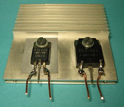
Reversing the two rectifiers for +5 volts and +12 volts. This modification is not a must. Sometimes an unwanted oscillation of the output voltage occurs, which can be avoided by adding an additional 1000 uF capacitor between ground and 13.8 volts.
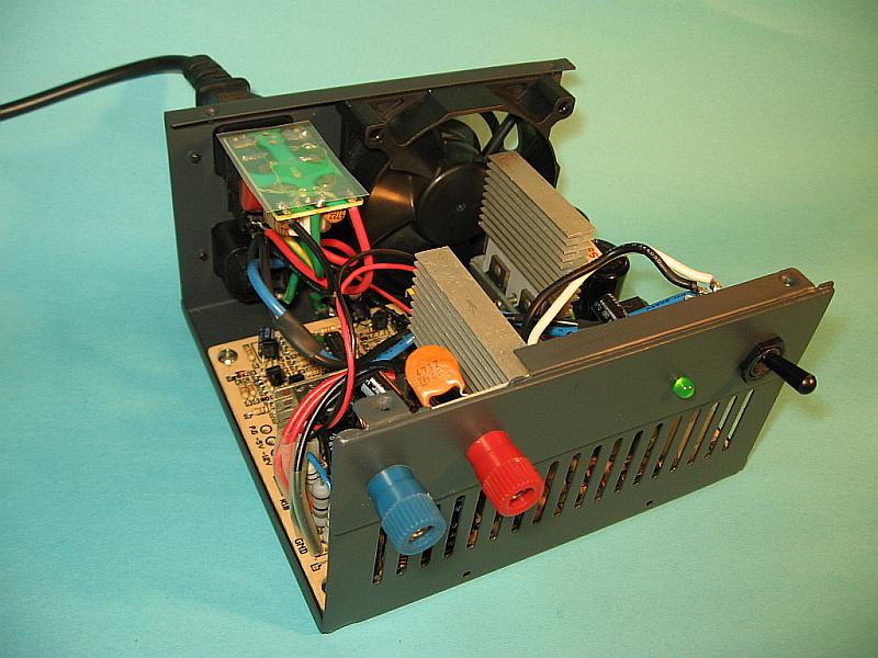
This is another modified PC power supply for my amateur radio transceiver. I have no noise on shortwave caused by the power supply, if the PCB is grounded to the metal case.
Another solution for ATX-PSUs: A different voltage divider serves as well and needs less current.
1. Between “red (5 volts)” and “black (ground)” I placed two 100 Ohm resistors in a parallel configuration.
2. Between “red (5 volts)” and “yellow (12 volts)” I placed one 2k2 and one 100 Ohm resistor in a parallel configuration.
The result was an output voltage of about 14.2 volts. See next picture. More details and pictures here.
Another example for ATX-PSUs. The output voltage about 14.2 volts.
This is the voltage divider on the printed circuit of an ATX-PSU.
The new wiring on the copper side.
A look inside the modified ATX-PSU.
Reducing the fan speed: Normally you don´t need the full speed of the fan. Therefore you can reduce the fan speed. I run the fan with 5 volts you get from the -5 volts power supply. A drop of of motor oil on the fan bearing reduces also the fan noise.
Cleaning the power supply: Used power pc power supplies are full of ugly dust and dirt. Take apart the power supply and wash it in a dishwasher before you modify it. After this treatment the power supply looks like a new one. I am not kidding. It works.

You can clean used und dirty pc power supplies in a dishwasher. Drying takes same days.
How to modify the case? The front of the modified power supply looks better with a peace of PCB. Here you see more pictures how to adapt the housings.

A piece of PCP is super-glued on the front.
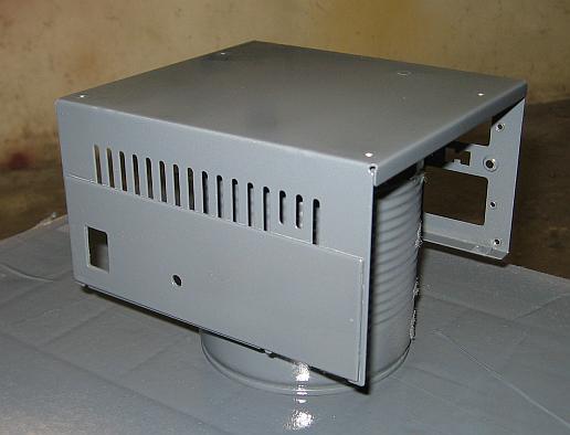
Revarnish the housing with aerosol lacquer.
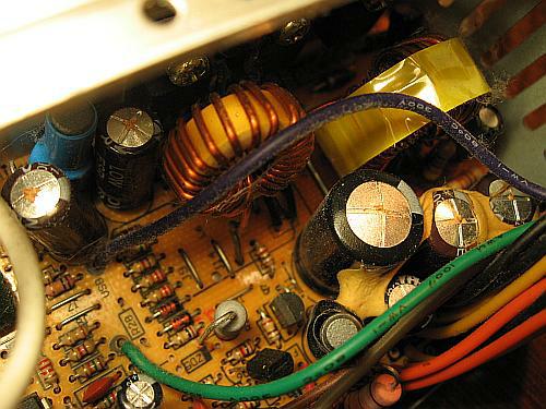
Electrolyt capacitors with broken safety valves on the top has to be replaced (Capacitor plague).