DVB-T-USB-Sticks as Scanner from 9 kHz to more than 1 GHz
For some Euros I ordered from a Chinese EBay-seller two DVB-T-USB-sticks. They are based on the receiver chip RTL283U. In combination with free Software and a simple up converter this dongle gives access to the frequency range from 100 kHz to more than 1 GHz. This means, that you can use those sticks as broadband scanner or low cost spectrum analyzer with limited accuracy.
DVB-T-USB-Stick: DVB-T-receivers in a USB dongle are low cost products for the reception of DRM+, FM and DVB-T. Theoretically you need only a small antenna. Provided the dongles inside is based on the chip RTL283U as the most of them are, you can make o loft of receiving experiments. You only need a freeware decoding software which you can download from the web. I ordered my stick from China on Ebay. After some weeks the tiny thing arrived in my letter box.
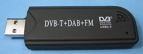
A DVB-T-stick for less than 10 Euros based on the tuner chip R820T in combination with the decoder chip RTL283U.
A mysterious loose contact: When I touched my exemplar the USB port looses contact to my PC. So I had to restart the unit. The reason was a loos contact of the USB connector. I could solve the problem by squeezing together the USB plug so the connectors fit tightly together. It was not a driver problem and it was not a problem with RF intereferences. Sometimes the solution is very easy.
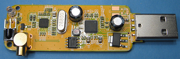
A DVB-T-stick with removed housing. Inside appears the tuner chip R820T and the decoder chip RTL2832U.
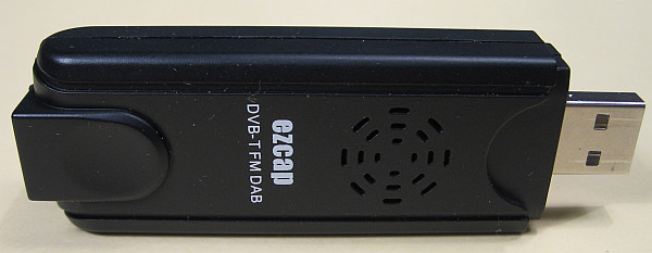
Another DVB-T-stick based on the tuner FC0013 and the decoder RTL2832U.
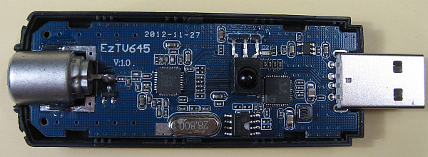
The same DVB-T-stick without housing based on the tuner FC0013 and the decoder RTL2832U.
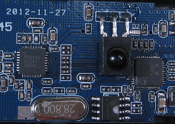
Close up of the printed ciruit board: On the left side the FC0013, on the right side the RTL2832U.
Minimum hardware- and software requirements: 1.7 GHz CPU, USB 2.0 and Windows XP.
Frequency range: According to the sellers information my exemplar is based on the tuner chip R820T. On http://sdr.osmocom.org/trac/wiki/rtl-sdr is a list of many tuner chips. According to this list the chip R820T has a frequency range from 24 to 1766 MHz. On the market exists DVB-T-sticks with different tuner chips. This means they are specified for different frequency ranges. The most of Ebay-sellers inform you about the chip sets of there offered products.
Reception below 22 MHz with the help of an up-converter: If you want to receive on shortwave or below 22 MHz you need an up-mixer. The most of the tuners are not able to receive below 22 MHz. On http://www.george-smart.co.uk/wiki/FunCube_Upconverter is the description of an up-converter. Its local oscillator works on 100 MHz. So the output frequency is 100 MHz higher than the input signal. In stead of 100 MHz you can use 40 MHz or any other frequency between 40 and 120 MHz.
Reception below 22 MHz without an up-converter by hardware modification: This is possible according to http://www.rtl-sdr.com/rtl-sdr-direct-sampling-mode/ and http://superkuh.com/rtlsdr.html#directsample. Only a few steps are necessary:
Open the housing of the stick.
Solder a thin wire directly to the pin 1 or pin 2 of the RTL2832U.
Connect this thin wire with the antenna.
Change the configuration of the software SDR# to “Direct Sampling”.
Theoretically the possible frequency range is now from 0 – 30 MHz. The details of the modification are shown on http://yu3ma.net/wp/wp-content/uploads/2012/08/rtl2832u-dc-mods.pdf. It is recommended to modify another stick for security reasons. By the way you don´t need to desolder the two coupling capacitors. You can leave them on the printed circuit board.
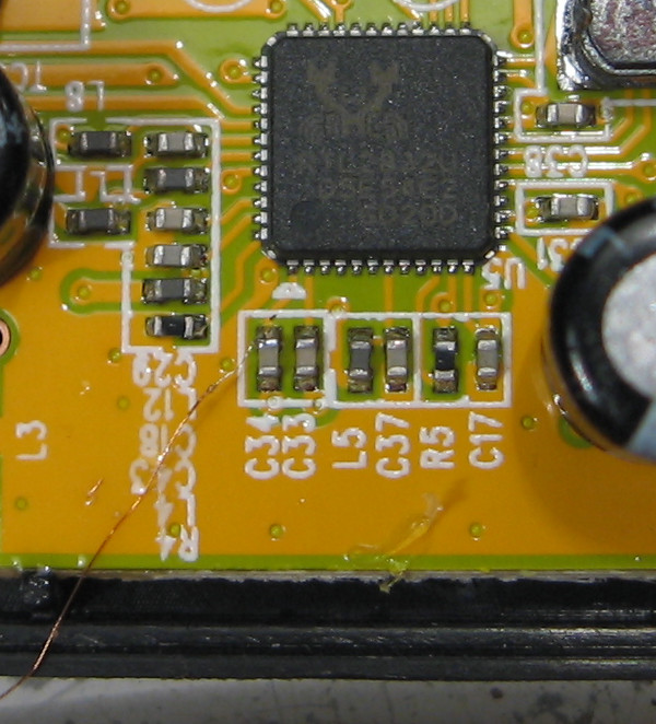
A thin wire soldered to pin 1 of the RTL2832U works as antenna and achieves the reception below 22 MHz without upconverter or additional hardware.
Software: From the internet you can download a large amount of free software solutions, which work together with DVB-T-sticks based on the RTL2832U chip. The installation procedure is almost the same. First you have to install the driver for the stick with the help of the software called Zadig. Thereafter you can install the decoding software, for instance SDR#, which is very easy to install. SDR# needs some additional DLL-files in order to succeed in communicating with the stick.
SDRSharp (SDR#): My favourite decoding program. Download on http://sdrsharp.com/#sdrsharp Very easy to install and the general user interface is clear without unnecessary features. It is recommended for beginners. Hints for installation:
http://www.essexham.co.uk/news/realtek-sdr-pc-dongle-for-under-20-pounds.html
http://rtlsdr.org/softwarewindows
SDR-Radio: Download: http://v2.sdr-radio.com/. How to install: http://www.hamradioscience.com/alternate-rtl2832u-install-for-sdr-radio-com/
HDSDR: Download: http://www.hdsdr.de/ Installation: http://www.hamradioscience.com/alternative-installation-procedure-for-rtl-sticks-and-hdsdr/
SDR-Radio: This software provides a lot of featuers. Sometimes the meaning of the buttons and displays are not easy to understand.
Reception of digimodes: SDR# is not able to decode digimodes. With the help of a special software (http://vb-audio.pagesperso-orange.fr/Cable/index.htm), which provides a virtual audio cable, you are able to use the well known digimode software solutions as Fldigi, DREAM and so on.
Reception of DVB-T and DAB+: The DVB-T-dongles used to be delivered with a small CD, which contains a reception software for DVB-T and DAB+. You cannot use this software and the other decoding software on the same pc. Before you install on of them you have to remove the other one. It is very important to create a restore point on windows before you install the software. Otherwise everything is mixed up and nothing works.
Broadband antennas for receiving:
MiniWhip: http://dl1dbc.net/SAQ/miniwhip.html ( 10 kHz – 20 MHz )
Discone: https://www.google.se/… discone+antenna+design
My first reception experiments without converter: The installation of SDR# was easy with the help of the installer provided on http://sdrsharp.com/downloads/sdr-install.zip. You should follow the instructions on http://rtlsdr.org/softwarewindows. The driver installation is included. You don´t need Zadig for the driver installation.
The USB-DVB-T-stick is delivered with a small antenna, which is almost useless. I cut of the antenna cable and connected it to an antenna amplifier made of a MMIC. As antenna I used a dipole with 2 x 2 meters. The sensitivity of this construction was now as good as a normal analogue FM-radio. However some dropouts occurred.
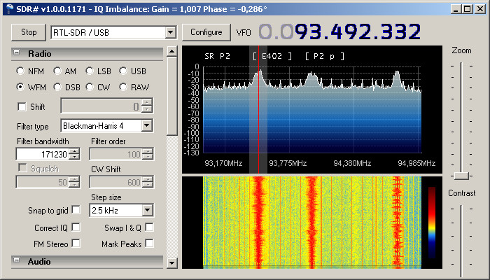
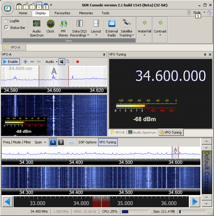
SDR# is receiving the FM-broadcast. This software is easy to operate and has GUI, which is easy to understand.
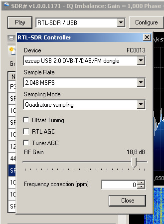
In “Configure” you can tune the sensitivity of the receiver. The higher the sample rate the wider is the frequency range displayed on the waterfall or frequency spectrum. You can display up to 4 MHz.
I tried to receive DVB-T, FM and DAB+. Therefore I used the software, which was delivered with the stick. With my homemade indoor-antenna I received some TV-Stations. DAB+ does not exist in my area. The reception of strong FM-broadcast-stations was noisy. In comparison SDR# receives much better FM-stations with less noise.
Reception from 9 kHz to 25 MHz with my homemade upconverter: One day I was in the mood to build my own upconverter. I took parts from my junk box. The mixer is a SA612, which has a gilbert cell and the local oscillator (LO) is 33.33 MHz TTL-oscillator. In the beginning I did not use any input filters. The performance was not outstanding. However I was satisfied with a 30 meter long wire antenna. SSB-stations were difficult to decode. However you can use this upconverter for the alligment of narrowband filters.
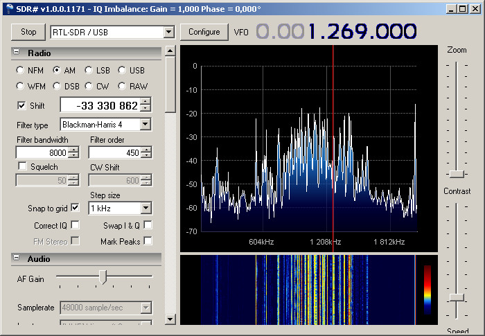
Scan form 0 Hz to 2 MHz with my homemade upconverter.
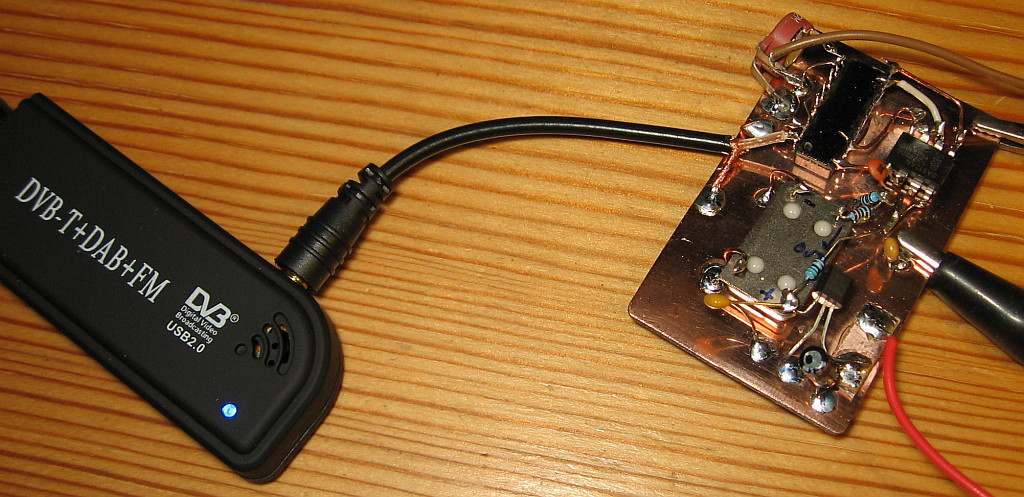
A DVB-T-Stick is connected to my homemade upconverter.
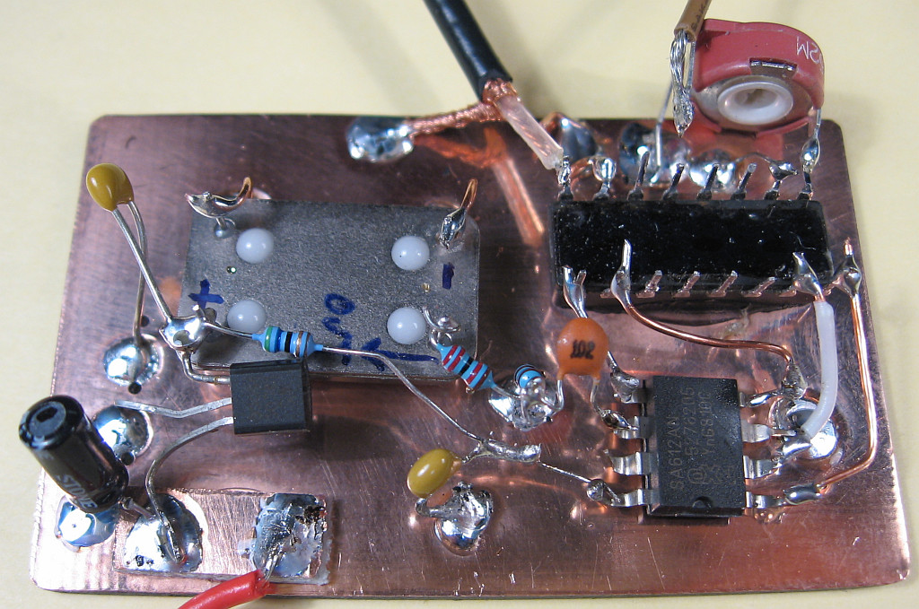
My first upconverter is made with the manhattan style technique.
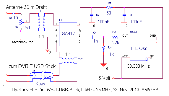
The circuit diagram of my first experimental construction. The circuit is not optimized yet and only the first draft. However it works pretty good for the reception of broadcast stations in spite of the lack of input filters. Weak signals are blocked by strong broadcast stations. Furthermore the input- and the output-impedances of the SA612 are not correct. A double balanced high level frequency mixer would be the better solution.
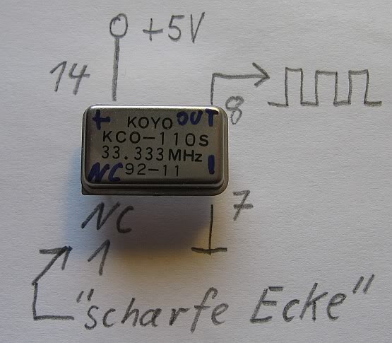
This is the wiring diagram for the most of TTL-oscillators. Some types need a supply voltage of 3.3 Volts in stead of 5 Volts. The meaning of “NC” is “no connection”.
My upconverter don´t have an input filter. That’s why it is not suitable for weak signals from amateur radio stations. However the much stronger broadcast stations are no problem. On VLF I could receive stations on 20 kHz and the time signal station DCF77 was clear to receive. As a matter of course longwave is good to receive.