Audio Amplifier using TBA820M with PCB
This is a very simple audio amplifier with up to 2 Watt output power. I use this amplifier to drive my speaker with the soundcard. The sound is in excellent quality.
Circuit diagram:
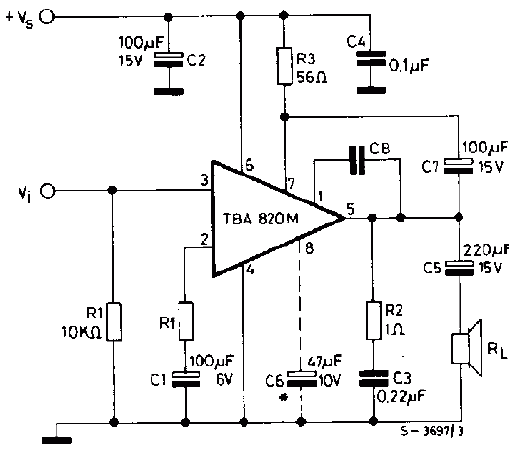
There is nothing special with the shematic of this tiny amplifier. The capacitance of CB = 220pF, C6 is not necessary. With C6 you have a better linearity. The resistance of R1 is between 10 k und 50 k. Rf has about 33 Ohm.
CB ist responisble for the upper frequency limit. If CB = 220pF, the bandwith of the amplifier is 20 kHz, with 680pF, the bandwith is only 7 kHz, which ist suitable for AM-Radios or shortwave receiving. The voltage supply Vs ist 9 to 15 V.
How to connect the potentiometer for the volume control? The resistor R1 can be replaced by a potentiometer of 22 k to 47 k for the volume control. Be aware of that you have an oscillator without any resistor R1.
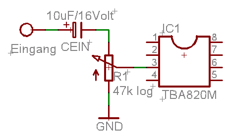
Circuit diagram for the connection of the volume control.
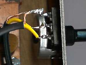
How to connect the schielded cables on the potentiometer for the volume control.
Printed circuit board: I created a small PCB with Eagle for one layer and wired components.
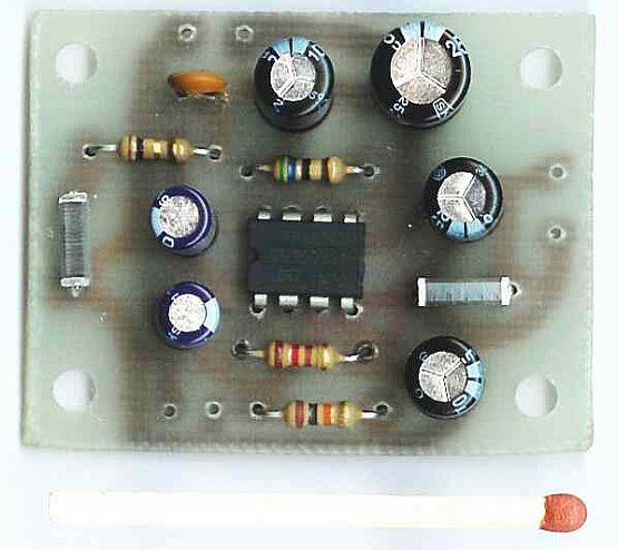
The tiny PCB in comparison with a match.
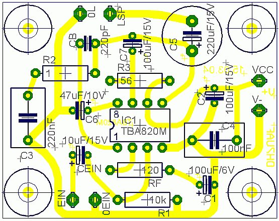
The component side of the PCB.
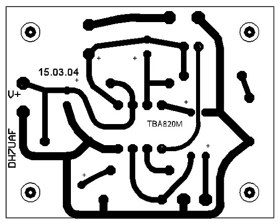
Soldering side of the PCB.
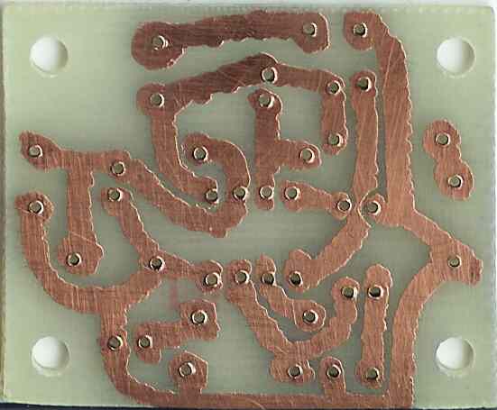
The soldering side of the PCBs prototype. I draw the lines with a permanent waterproof marker. Then I placed the board in the FeCl-Solution in order to dissolve the unwanted copper.
Some links:
– datasheet TBA820M
– BRD-file for the layout with Eagle
