An old switching power supply which was originally intended for use in coffee machines, supplies 21.5 volts. Now it appealed to build me a power supply with adjustable voltage. Below, I want to offer a general guide how you can modify an unknown switching power supply with a little luck and what is to be observed. For very little money, then get a powerful power supply for the electronics workshop. It is short-circuit protected, by the way. Unfortunately lacks an adjustable current limit which could protect experimental electronic circuits from the smoking.
How to do with a little detective work and experimentation: In an unknown power supply for which I could find no schematic, sits a L4975A as switchers. The data sheet of the L4975A proposes an application (see page 18, Figure 35, 18kOhm Poti) for a variable output voltage, which is determined by the value of the resistance. I could locate this resistance on the circuit board of the switching power supply. To, I took an ohm meter to help, since not all traces on the multilayer PCB is visible. To give me confidence, I soldered another one parallel to the decisive resistance. The voltage drops then as expected. The smaller the total resistance value, the smaller is the voltage.
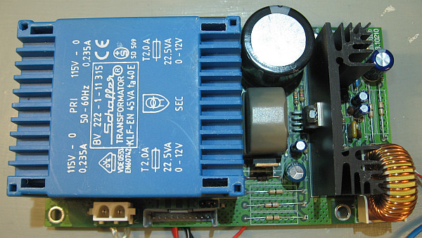
This switching power supply was originally intended for a coffee machine. Since the key electronics einschliießlich of the transformer is housed on a printed circuit board, the usage will save much work this Electronics Assembly.
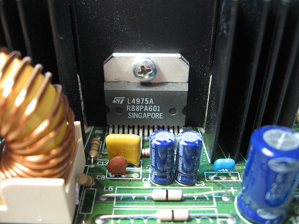
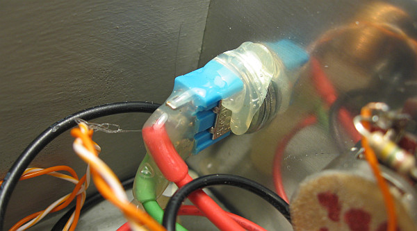
The crucial switching rule L4975A. Right next to the throttle resistance is already out soldered to replace him with a potentiometer for the voltage setting. See image below.
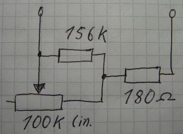
With this circuit, the said resistance was replaced to meet the voltage range. The total resistance can be adjusted between 180 ohms and 61.2 kOhm.
I replaced this resistance then with a potentiometer. To meet the exact area, still a resistance had to be paralleled this Poti and another in series. I determined by trial and error and calculate the values.
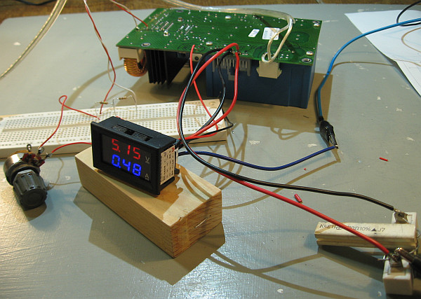
Flying test setup with power voltage indicator and load resistance for the base load. In the background the switching power supply.
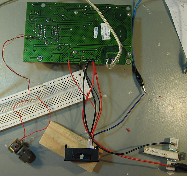
View of the test setup from above.
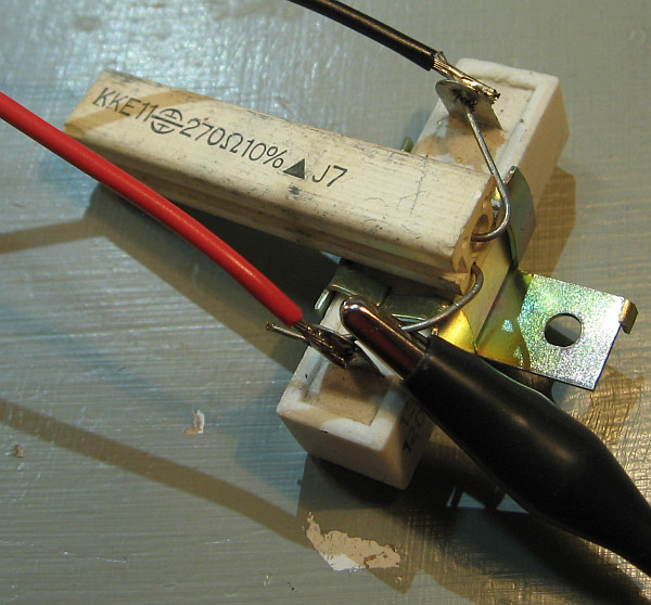
Unfortunately, switching power supply requires a basic load, because it’s otherwise starting to tick and pelting. A parallel connection of a 120 ohm and a 270 Ohm resistance, what I found by trial and error served as base-load.
The switching power supply not ticking, chatters or vibrates, a base load is necessary, which is to determine through experiments.
Pulses of 600 are superimposed at a frequency of approximately 200 kHz output voltage mVss. Counter clock chokes and capacitors I could suppress the impulse to about 60 mVss. Here too you must experiment.

Interference pulses on the output voltage are unfortunately typical of switching power supplies.
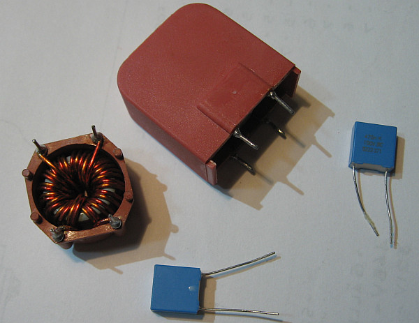
Counter clock chokes and capacitors I could suppress mVs of 600 mVs to about 60. Best the throttle left went into the picture, because to her, the voltage drop is just 0.1 Volts at 1 amp. Thus, I could operate the power supply on a long wave radio to FM. However, some slight errors were audible. The power supply is not particularly suitable for the operation of radio stations.
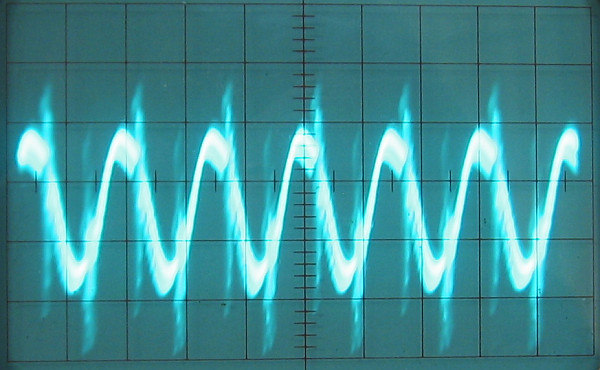
50m VSS on the output voltage according to the installation of the counter clock filter with the two capacitors each 200nF.
A combined indicator is used for the current and voltage display, as described under LED-current voltage display in the mounting frame . The Antec has still 5 volt output, dr is offered one for operation of the LED display.
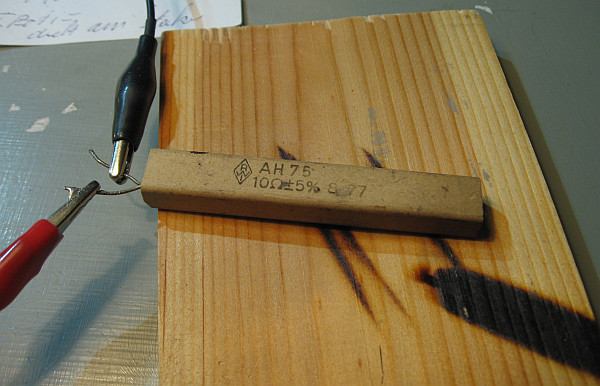
A 10 Ohm resistor, which produced burn marks on the wood surface at 20 volts through his heat to test as a load. A tin can would be better as a base.
Housing and mechanical structure: After the experiments, then came the arrangement in a housing. It consists of wooden slats, plywood and footboard. The painting consists of ground color. I took what was available. Gray ground color has proved to be particularly productive, as she can be easily applied with a brush and dry quickly.
For the production of the housing I came on 80 holes, if I myself did not count. Of them, 48 for ventilation on the back and on the cover were necessary.
The power supply works without protective conductor: Therefore, there are security concerns. The front plate is made of aluminum. The wires to the switch could be loose and touching the front panel. Then would the full mains voltage on the front panel. Therefore, I’ve isolated the Löststellen with hot glue to exclude this unlikely event. Who want to go sure, used a protective earthing conductor for the front panel, making it on the safe side. However, it is also not sure whether the protective conductor behind the socket is actually properly. You leave to build not only on the Earth. Is the device just for me in this State and I will use no other. In the future I will reasons therefore make a proper wiring of power supply, use a different switch and connect the front panel to the protective earth conductor.
Air: The power supply unit is warm at full load. Therefore, I’ve drilled on the back and the cover ventilation holes. As a result, the warm air can rise to the top and fresh air can flow from the back. The internal temperature is 31 ° C at an ambient temperature of 20 ° C at 3 amps and 18 Volt load. Therefore, the power supply can handle this load as permanent load.

Internal view with counter mode choke filter bottom left angegracht. This is just a sine of 50mVss the output voltage, 200 kHz overlaid (click on the image for a larger view). The two capacitors of that filter have about 200nF. Prefabricated electronics assemblies save you lots of work.
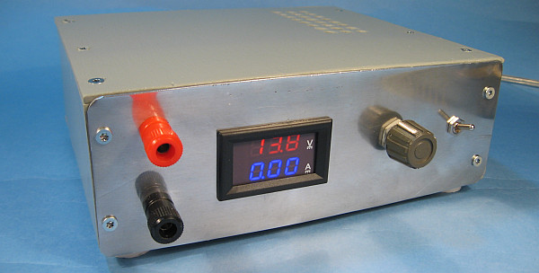
Front. Total weight of the power supply: 1.85 kg. The front consists of polished aluminum sheet and requires no painting.
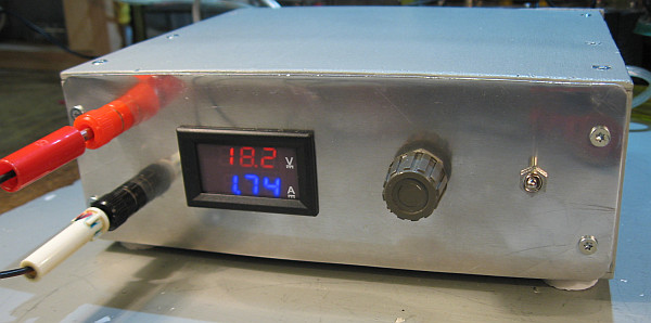
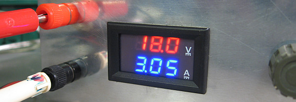
Power supply in operation at 18.2 volts and 1.74 amp load.
The connections of the power switch are sealed for safety with hot glue, because the front consists of footboard.
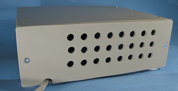
The back has received ventilation holes. How to: Template with graph paper, punching in, drill at high speed, painting with brush, refinishing with cotton swab into the holes. The better the cooling, the longer is the life of electronics, particularly semiconductors.
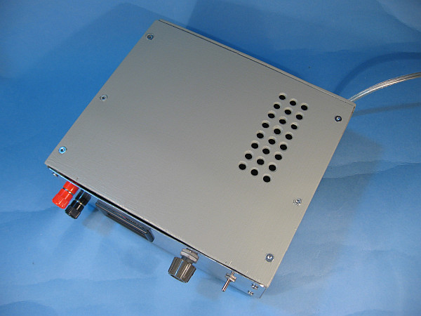
Finally, the lid has received also 24 holes with diameter of 6 mm, placed directly over the heat sink. The warm air can selectively pull upwards. Cold air flows up through the back. At 18 volts and 3 amps, the internal temperature rises to 31 ° C.
At room temperature, a continuous load of 18 volts and 3 amps is no problem thanks to the ventilation on the back and the cover.
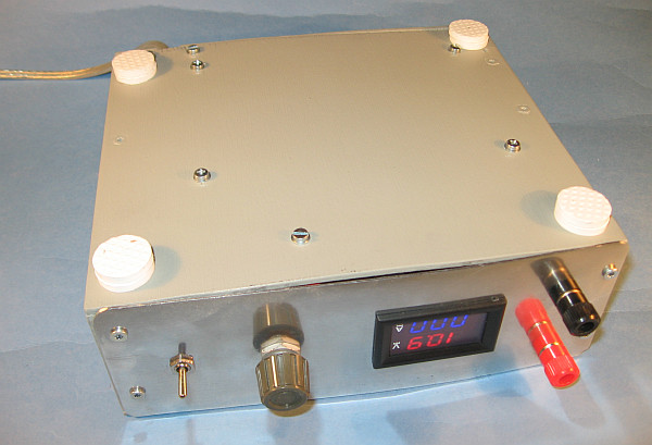
At the four corners, two stacked feet are located so that the screw heads can not scratch the surface.