This DIY project generates a sine wave and a square wave signal from 1 Hz to 40 MHz using the DDS module AD9850. The DDS module controls the microcontroller ATmega328. The firmware is present as Arduino sketch, which is customizable to your needs. The material cost is less than 20 euro. This generator with provided with amplitude modulation.
In principle it is a replica, which on
http://www.vwlowen.co.UK/Arduino/AD9850-waveform-generator/AD9850-waveform-generator.htm
with the PCB layout, is fully described the firmware and the circuit diagram.
The local page provides all information on the wiring of the circuit with some consideration. It is recommended to use a printed circuit, as listed on this page there as exists in the layout.
Because I was missing circuit board as the base material with photo positive coating, I decided for a design on a grid plate. This works of course. However, the risk of wiring errors is large. Finally, some connectors had intermittent contact, whose time-consuming troubleshooting clouded the joy of crafting. The production of a printed circuit board saves time and simplifies the replica.

Replica of the DDS sinewave generator on a Breadboard (larger view click on the image).

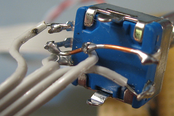
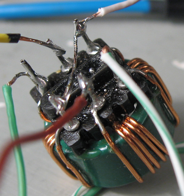
A replica of the DDS generator on grid plate is recommended for brave with plenty of time. The individual wires of a tinned power cable served me as a wire. The brown white cable uses the sine wave signal.
What is DDS? DDS is described in https://de.wikipedia.org/wiki/Direct_Digital_Synthesis . Simplified considered DDS modules process analog signals using digital signal processing. Their inputs and outputs have analog-digital and digital to-analog converters. In addition, the computer architecture for the operations of digital signal processing is optimized. You must not know exactly how, if you attack to ready-made libraries.
Procurement of materials, component list, and costs: All components available are in the Bay. The material costs keep under 20 euros in borders.
is fitted with the exact names and article numbers, which form the basis of this project. Other vendors and dealers usually provide these products.
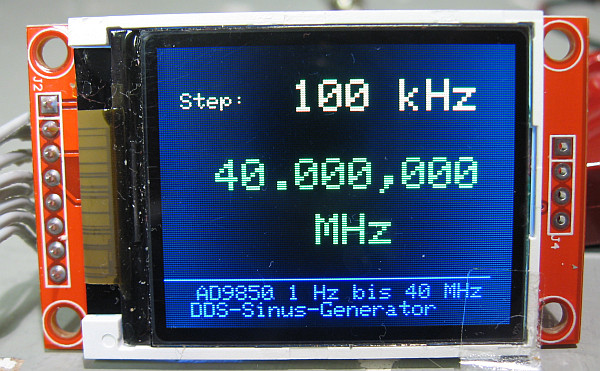
The software I slightly modified allows a coating from 1 Hz to 40 MHz. A TFT LCD display module ST7735S is used.
Operation: Via two rotary encoder, which have moreover a push button function, the frequency of 1 Hz can be up to 40 MHz a 1 Hz set. Various step sizes from 1 Hz to 500 kHz are available.
Operating the DDS sine square generator (source of videos: YouTube user vwlowen).
Obtain software and libraries: The original software is limited by 10 Hz to 10 MHz. A few small amendments allows
This Arduino sketch for AD9850,
the we just in the Arduino IDE copy, a cover of frequency from 1 Hz to 40 MHz. Before compiling and burning do not forget to include the three necessary libraries. We download these three libraries from Github as zip files:
– https://github.com/adafruit/adafruit-GFX-library
– https://github.com/adafruit/adafruit-ST7735-library
– https://github.com/brianlow/Rotary
Click on the green button “clone, or download” on Github and then click on “Download Zip”. The zipfiles can then be included in the Arduino IDE. You have to be to unzip.
The ATmega328 burn: How these libraries, and software (the skit) in the software Arduino IDE enters, is completely under
Getting started with the Arduino UNO R3
described. The Arduino UNO R3 serves in this case as the ATmega328 USB programmer.
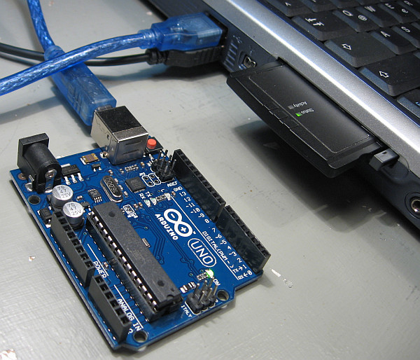
The firmware on the Atmega328 arrives with an Arduino UNO R3, which is available for a few euros in the Bay. The software Arduino IDE is installed on the computer.
In addition, it is important that we get an ATmega328 plug-in inside, which is prepared with an Arduino bootloader. Also they are available in the Bay.
Pin assignment of the encoder (rotary switch): The encoders are standard versions, equipped with a push button, are pressing on the axis cause. The encoder itself has only three connections. The wiring itself is to be inferred from the comments of the two following images.
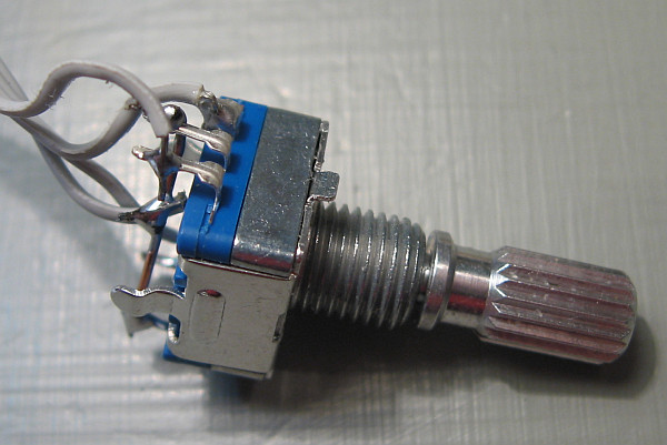
One of the two encoders (rotary encoder) push (push button function) and 6 mm axle with ratchet settings. The procurement is also described in the component list. The mounting nuts and washers are of course included.
Example of wiring of the left rotary encoder. The temple is the ground connection. The right connections are responsible for the push button. Three connections are left. The medium of which belongs to the crowd. The other two are of the rotary encoder.
Experience: After my measuring equipment the AD9850 module has just hit on the Hz the frequency, so that is surely a calibration of the software. The amplitude of the sine is approx. 1 VSS, that of the rectangle 5 VSS. The sine is overlaid with me with a DC voltage, which is why a coupling capacitor is recommended. The author of the original software was no longer satisfied with the quality of the sinus above 10 MHz. Remedy may create an additional low-pass filter as the anti-aliasing filter. On the DDS module, there is already an output filter.
At supply voltages of more than 8 volts DC for the entire circuit, the 5Volt-Spannugsregler should be provided with a small heat sink. The power consumption is 180 mA.
At 40 MHz, the highest frequency, the sinus is slightly deformed. This can be but also to my old weak 150 MHz oscilloscope.
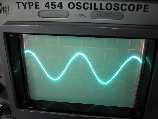
Sine wave at about 1 MHz. The amplitude of 1 VSS (1 volt peak to peak) is fairly constant over frequency.
Unfortunately, stores the software not the last saved value and always starts with 1 kHz. A signal is generated only if one of the rotary encoder is pressed. Until the image on the display appears after switching on, it takes a few seconds. Only a bright, white surface appears a loose connection of the connector is likely.
Where do I out the sine and the rectangle signal? The comment of the following picture explains this.
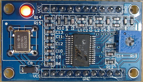
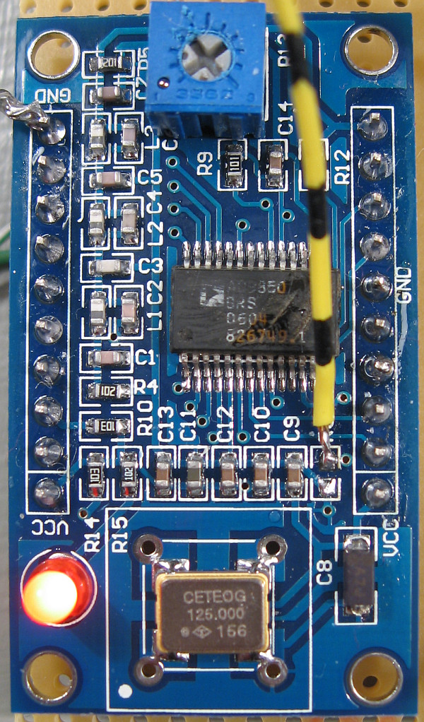
The AD9850 DDS module: Counted bottom row from right to left: pin 1 and 2: sine wave signals 1 VPP. Pin 3 and 4: square wave 5 VSS; PIN 5: Ground (GND). Right to see the blue potentiometer to adjust the pulse-pause ratio. The top row is mostly unused. Data sheet and diagram here. Therefore, pin 1, the right pin, is connected with the deep pass.
AM modulation for the AD9850 with 2N700: This is http://www.analog.com according to … TO 423.pdf pretty easy with a 2N7000. Refer to the following sketches and their comments. R6 must be removed on the DDS module to solder a wire on pin 12 of the AD9850 ICs. Supposedly, there will be modules where this PIN is deduced. For me, this was not the case. So I had to solder.
The responsible for the amplitude modulation connection RSET is located at pin 12 of the AD9850 ICs. PIN 12 with the 3, 9kOhm resistor R6 is connected to ground. We solder this resistor from and to see close as shown on the picture is a wire for the AM modulation.
After the resistor R6, no sine signal comes more from the module. Either we solder the tiny R6 again or we take one leaded 3 k 9 resistor, we connect somewhere with mass and the PIN 12. R6 is by the way a voltage of about 1.3 volts.
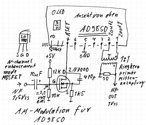
Sketch for the amplitude modulation with the AD9850 module, viewed from above, so the component side, here is where right the Poti to see would be and left the LED. Unfortunately, the PIN 7 not at all modules work. As described earlier, to R6 from solder then, to then solder a wire on pin 12 of the ICs AD9850.
For the AM modulation, the DC voltage connected to the RSET of the AD9850 module is changed. Analog device is recommended for a small circuit with a 2N7000 (N-channel enhanced mode MOSFET, enrichment type, self-locking). In the Bay I found 100 pieces of it for about 3 euros. Both RF outputs are executed via a small toroidal transformer, 1:1 turns ratio, primary the Center tap connected to ground. 10 turns per winding would have to submit to ferrite material. Take a small toroidal core.
AM modulation for the AD9850 only with passive components:
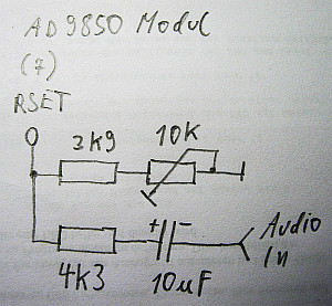
Alternative feed of the audio signal for the AM modulation, which should be absolutely linear also with this proven circuit. The 10 kOhm potentiometer is used for adjustment of the operating point. The release of the HF is again on the toroidal transformer, as it in the headed circuit is shown. RSET is the PIN 12 of the AD9850 ICs. The NF, the audio signal, required about 1 VPP. The circuit is a proposal by Ingo from the Wumpus-Gollum-Forum.
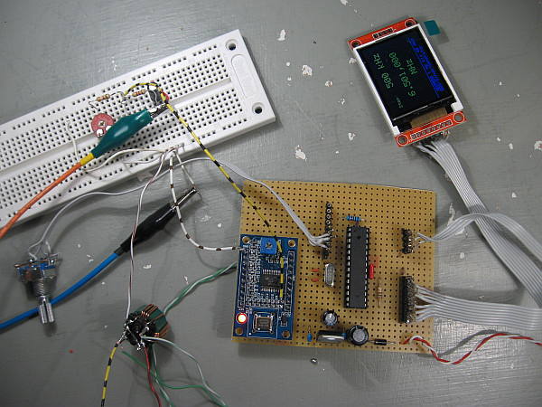
Experimental setup for the AM modulation. The yellow / black wire leads directly to the PIN 12 of the AD9850 ICs.
Power supply with 3 x 5 coils (3 x 70 uH) from the scrap box for the first attempt. The 5 turns are too little for under 2 MHz. The two Primärwickllungen phase interconnection, so that your composite inductance increases. The Rinkgern came only for test purposes to use. It has its maximum at 10 MHz.
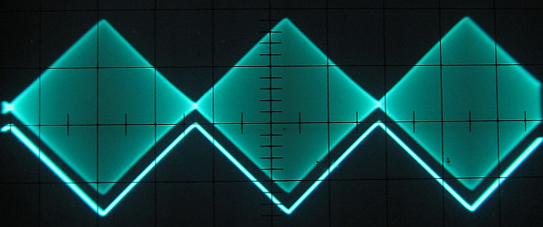
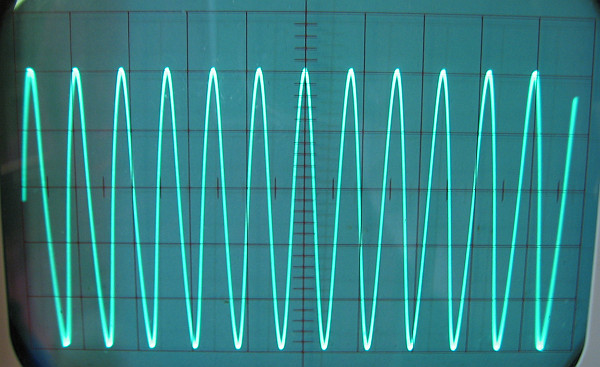
100% AM modulation with a triangle signal (below) for the evaluation of linearity in 10 MHz carrier wave. It is the resistance circuit used. I have just connected the HF transformer to the two terminals of the module, although a PIN is still the low-pass filter. It is anyway.
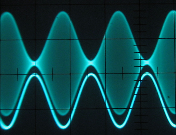
With an sine mplitudenmodulierter carrier.
No square-wave signal? For me, the DDS module provided no rectangle signal. In this case, one of two rotary encoders is only to push, so that even a sine wave can be generated. So long then twist the (blue) trim potentiometer on the DDS circuit board for the pulse-pause ratio until a signal and is the pulse-pause ratio 1:1.
The rectangle signal interferes with the sine wave signal: 10 cm wire at the outlet of the rectangular signal lead to visible distortion of the sine signal that kHz are noticed as well around the 700. The errors are extreme, if the rectangle outputs are touched with a watchmakers screwdriver. Who wishes to receive a possible clean sine wave signal, the rectangle signal switches off best. This goes through twisting of the trim pots up to the stop. Visible distortion of the sine signal come from so of the rectangle signal and are not a consequence of the digital waveform generation. Of course, shielded signal cables and a good ground lead should be used. The following two spectra with off rectangle:
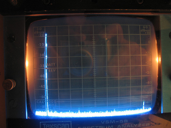
Range at 30 MHz output signal, dB indication left, 10 MHz / Division.
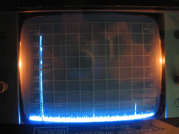
Spectrum at 40 MHz. At 80 MHz is to realize a harmonious with-35 dB. At approximately 115 MHz, always a peak is to recognize, which probably comes from the clock generator.
I can’t share claims, the output filter of the AD9850 module would be worth nothing. There is however still a module with an AD9851 which is suitable to 70 MHz and has perhaps even better values.
Applications and extensions: The DDS generator can be fitted with its stable quartz frequency with an amplitude modulation, to spoof old tube radios a mediumwave transmitter. The output should be fitted with a buffer stage (E.g. emitter follower) and a reducer to provide an impedance of 50 ohms. Also, the buffer level protects the DDS module against destruction.
Other applications: Quartz Rod parter LO for SSB-receiver, RF test transmitter or audio generator. Through a software extension, a frequency modulation might be to an analog input of the ATmega328 possible making the DDS-generator to the sweep.
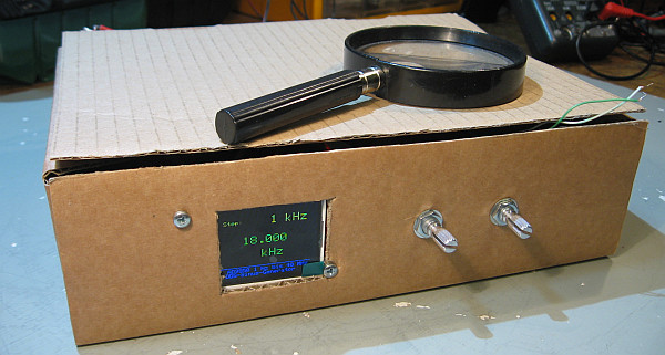
Because the project is not yet complete, a cardboard box serves as a protective case, not to speak of a housing.
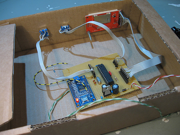
Interior of the temporary experiment, the just order in the clutter in the to bring.
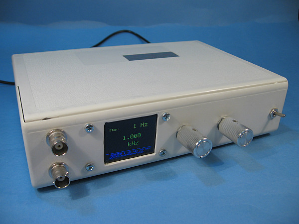
It looks better already. An old box of floppy disks is used as housing here.

There is still plenty of room for extensions. Of subsequently built-in heat sink for the voltage regulator is not to see in the picture.
AD9850 as a sweep generator – an idea for Outlook: As an extension to a Wobler a simple solution for analog Oscilloscopes I have in mind, that not all possess an external sawtooth output. The construction of external sawtooth generator is not a big hassle and makes sense, because its output voltage must be between 0 to 5 volts and should also use this area because of the resolution. Two pins are free on the ATmega328. Pin 28 is suitable for the sawtooth-supply analog and PIN 18 can be used with a pressure switch for the choice of hubs, to examine AM and FM if filter. The hub can be show on the display. The software plug-in is relatively easy.
A buffer stage (E.g. emitter follower) at the output is strongly recommended so that you don’t accidentally break the output of the AD9850.
A control loop with slow time constant would stabilize then with the help of the input of the output level.
After all, you would then have a nice test transmitter for AM, FM and wobble, which is suitable even for the NF area.
Extension and renovation on up to 70 MHZ with an AD9851 module The AD9851 costs a few euros more and can produce up to 70 MHz frequencies. The software needed a minor adjustment in accordance with http://www.rocketnumbernine.com/2011/10/25/programming-the-ad9851-dds-synthesizer , since the AD9851 with a higher clock speed. There are two modules with the same Board (E.g. search for 272491356349 in the Bay). Under
http://elektronikbasteln.pl7.de/ad9851.html
is the conversion for an AD9851 described.